Case Study: Goods Inwards NdFeB Magnet Tests
Overview
Magnet Methods supported a customer in providing test limits for a Gauss probe based goods inwards check on large NdFeB prism magnets. Our customer had reported bigger than expected differences between spot measurements taken on opposing faces of the magnets.
We also found the measurement results surprising, and investigated the possibility that this could be caused by a variation in properties throughout the bulk of the magnet.
Project Scope
- Understanding of magnet manufacturing processes
- 3D FEA modelling
- Special technique for model setup
- Supply of reliable pass/fail test limits
Application
- Goods inwards testing of permanent magnets
- Best practice measurement of magnet performance

Direction of Magnetisation Variation
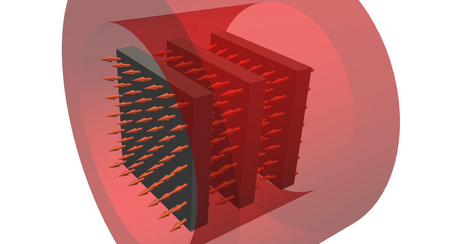
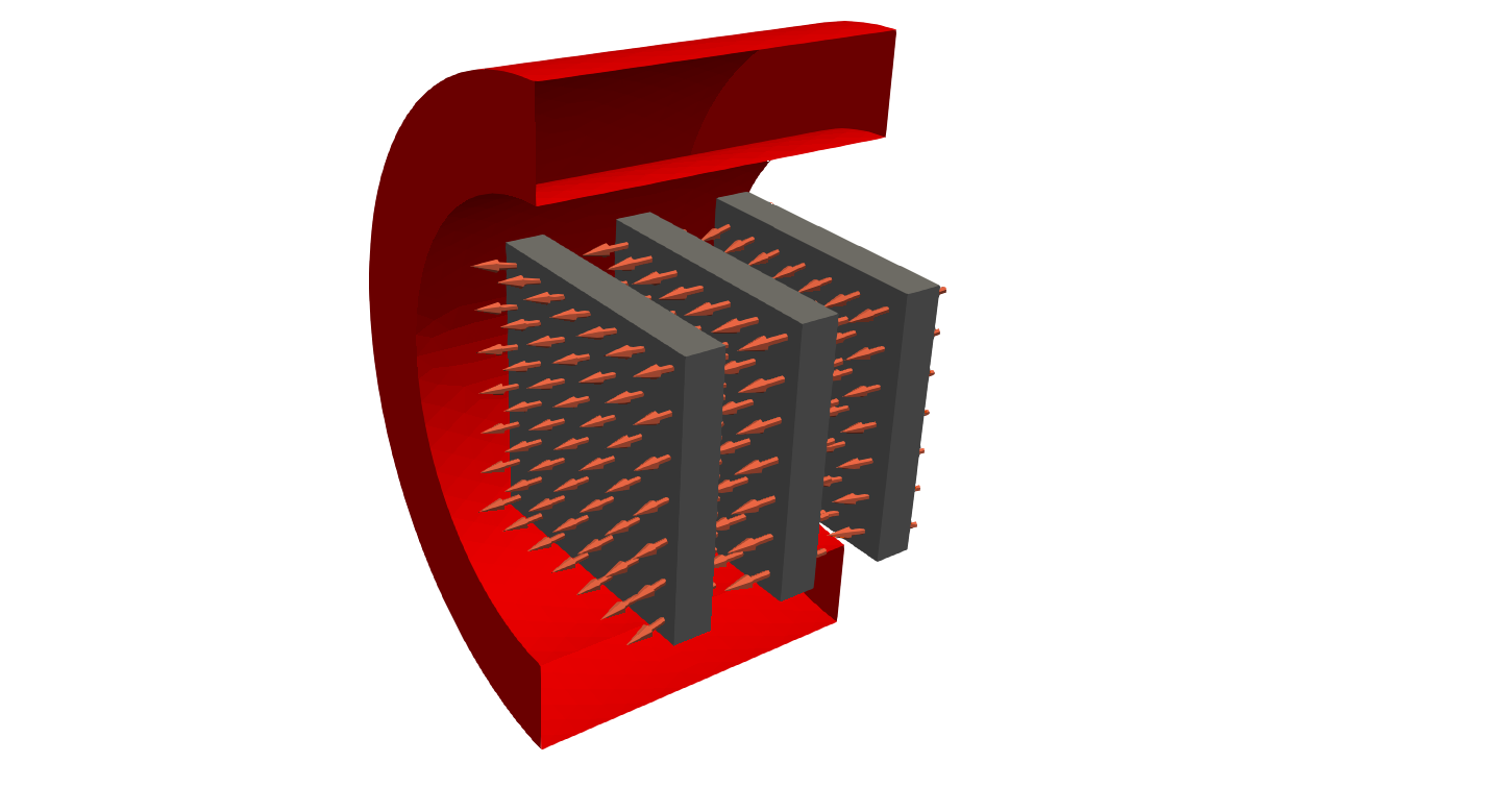
During the magnet manufacturing process, fine particles of magnet material are pressed into a single block in the presence of an aligning field. The anisotropic properties created by this iso-static compression are not completely uniform. The solenoid producing the aligning field will produce near-axial B near its centre, but the direction of B, and hence the anisotropy axis will flare towards the ends of the solenoid. This flaring of the field direction will produce a corresponding variation throughout the sintered block from which individual magnets will be produced. The plot shows the aligning B vector in the middle and end slices. Note that B vectors are near-parallel and closely aligned with the axis in all of the middle slice, but not in the end slices, where considerable flaring can be seen especially at the furthest off-axis locations.
For small magnets, this means that the orientation of the magnetic axis could vary with respect to the magnet geometry, depending on where individual magnets are cut from the block. Five degrees is a standard tolerance, but for critical applications, a two degree tolerance (and associated increased cost) can be achieved by using only material near the centre of the block.
For large magnets, where perhaps only one magnet can be produced per “slice” of the block, this means that a variation of up to 5 degrees in direction of magnetisation could be present within a single magnet, if it is cut from one of the end slices. If the magnet is cut form a central slice however, the direction of magnetisation will be near-parallel and normal to the magnet surface throughout the magnet volume.
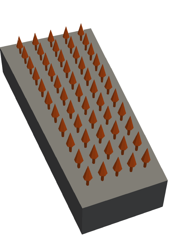
The plots here show direction of magnetisation for a large prism magnet. The LH plot shows a parallel magnetisation, typical for a central slice of the sintered block. The RH plot shows a typical magnetisation for the same magnet cut from an end slice of the block. Note that the vector “flare” is exaggerated here for clarity, but in practice would be less than 5 degrees at the extremities of the magnet geometry.
Analysis Method
A single symmetry plane was used for a 3d finite element model of a trapezoidal prism magnet in air. As such, the 3d model was simple, except that the magnetisation axis was defined as a function of position within the magnet volume. Magnetisation axis orientation was assigned on an element-by-element basis up to a maximum of 5 degrees from the magnet surface normal. The element axis orientation was prescribed using a simple APDL (Ansys Parametric Design Language) script.
Results and Conclusions
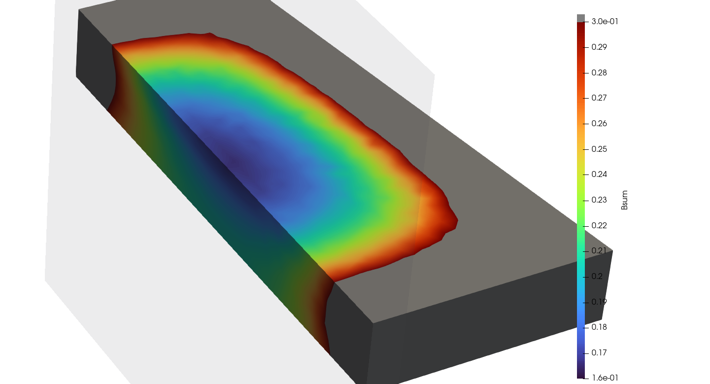
The plot shows the variation in modulus of B over the magnet surface, and through the magnet volume at the symmetry plane. Note the increase in |B| from top to bottom, which for a 5 degree maximum variation in magnetisation axis, was well over 20%. We used the 5 degree standard tolerance, in addition to other material and geometric tolerances, to provide some acceptance test limits.
The analysis showed that although a spot face measurement of |B| using a Gauss probe is simple, it has its limitations. Single axis probe orientation is critical, as is the exact position on the magnet face, although it can give repeatable results for large magnets with smaller spatial rate of change of B.
Any within-tolerance variation of magnetisation direction complicates things significantly when it comes to applying test limits, even though the vast majority of applications would be insensitive to it.
A better method is to use a Helmholtz coil with an integrating flux meter. If the coil constant is known, then the fluxmeter can provide a magnetic moment measurement, which is a very standard and un-ambiguous measure of a magnet’s “open circuit” performance.